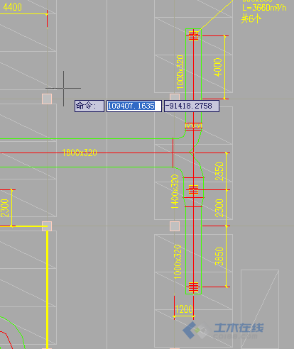
请教各位高手一个问题! 风管的调节阀按照什么规则安装?如果主管分出两个支管,是不是只需在一个支管上安装调节阀,另一个支管不需安装?此外,还有一种情况(见附图),主管分出两个支管,一个支管安装了调节阀,另一个支管没安装调节阀,但却在支管中间和末端开设了风口,如果这样的话,这两个风口风量是否能达到设计要求?
请教各位高手一个问题! 风管的调节阀按照什么规则安装?如果主管分出两个支管,是不是只需在一个支管上安装调节阀,另一个支管不需安装?此外,还有一种情况(见附图),主管分出两个支管,一个支管安装了调节阀,另一个支管没安装调节阀,但却在支管中间和末端开设了风口,如果这样的话,这两个风口风量是否能达到设计要求?
 2楼
2楼
理论上,如果水力计算精确的话,是不用设置调节阀的,设置调节阀的目的也就是弥补计算误差,或在实际使用中风量调节的不确定性,这也就是设置调节阀的规则。你举例的情况要看具体使用要求才能说清楚,一般不会是这样做的。
回复
3楼
谢谢您的指点!我举出的例子是在地下室汽车库,排风排烟要求不是特别精准,那就可以这样设置了?
回复
4楼
设风量调节阀的话 主风管是不设的,支路主要设。
有2种例外 如果支路只有一个风口可以不设;
如果2个支路的风口数量一致,排列的也比较均匀,可以不设。其他的就按上边说的就好了,一般遇到的都涵盖到了。
回复
5楼
学习了

回复
6楼
不认同此说法。为什么说主风管是不设的?
回复
7楼
设置风量调节阀的原因是害怕支风管没有风,所以只在支路设就好了。一共就那么多风量,支路的风量满足了,剩下的不就在主风管么?
回复
8楼
是否需要设置平衡风量阀是需要计算的:先用假定流速法算出最不利环路的压降,然后用等比摩阻法来确定并联环路的压降··············
[
本帖最后由 sept09 于 2012-2-19 08:02 编辑 ]
回复
9楼
具体方法:
The equal friction method of sizing ducts is often preferred because it is quite easy to use. The method can be summarized to
Compute the necessary air flow volume (m3/h, cfm) in every room and branch of the system
Use 1) to compute the total air volume (m3/h, cfm) in the main system
Determine the maximum acceptable airflow velocity in the main duct
Determine the major pressure drop in the main duct
Use the major pressure drop for the main duct as a constant to determine the duct sizes throughout the distribution system
Determine the total resistance in the duct system by multiplying the static resistance with the equivalent length of the longest run
Compute balancing dampers
1. Compute the air volume in every room and branch
Use the actual heat, cooling or air quality requirements for the rooms and calculate the required air volume - q.
2. Compute the total volume in the system
Make a simplified diagram of the system like the one above.
Use 1) to summarize and accumulate the total volume - qtotal - in the system.
Note! Be aware that maximum load conditions almost never occurs in all of the rooms at the same time. Avoid over-sizing the main system by multiplying the accumulated volume with a factor less than one (This is probably the hard part - and for larger systems sophisticated computer-assisted indoor climate calculations are often required).
3. Determine the maximum acceptable airflow velocity in the main ducts
Select the maximum velocity in the main duct on basis of the application environment. To avoid disturbing noise levels - keep maximum velocities within experienced limits:
comfort systems - air velocity 4 to 7 m/s (13 to 23 ft/s)
industrial systems - air velocity 8 to 12 m/s (26 to 40 ft/s)
high speed systems - air velocity 10 to 18 m/s (33 to 60 ft/s)
Use the maximum velocity limits when selecting the size of the main duct.
4. Determine the static pressure drop in main duct
Use a pressure drop table or similar to determine the static pressure drop in the main duct.
5. Determine the duct sizes throughout the system
Use the static pressure drop determined in 4) as a constant to determine the ducts sizes throughout the system. Use the air volumes calculated in 1) for the calculation. Select the duct sizes with the pressure drop for the actual ducts as close to the main duct pressure drop as possible.
6. Determine the total resistance in the system
Use the static pressure from 4) to calculate the pressure drop through the longest part of the duct system. Use the equivalent length which is
the actual length + additional lengths for bends, T's, inlets and outlets
7. Calculate balancing dampers
Use the total resistance in 6) and the volume flow throughout the system to calculate necessary dampers and the theoretical pressure loss through the dampers.
Note about the Equal Friction Method
The equal friction method is straightforward and easy to use and gives an automatic reduction of the air flow velocities throughout the system. The reduced velocities are in general within the noise limits of the application environment.
The method can increase the numbers of reductions compared to other methods, and often a poorer pressure balance in the system require more adjusting dampers. This may increase the system cost compared to other methods.
Example - Equal Friction Method
The equal friction method can be done manual or more or less semi automatic with a spreadsheet as shown in the table below.
The table is based on the diagram above. Air flow and friction loss from a diagram is added. Minor pressure loss coefficients must be summarized for for the actual applications.
The pressure loss in each path is summarized on the right and pressure loss is added manually in the dampers to balance the system.
回复
10楼
同意在支管上设置!!!!!!!!!!!!1
回复
11楼
一般的情况下是都要设置调节阀的,为的就是便于控制流量,从而达到精确控制的目的,你可以查查相关的规定。
回复
