2楼
2楼
The MINI-SUCKER
Air Actuated Oil Skimmer and Oil/Water Separator System:
Utilizing a floating surface oil pick-up and air pump, this system removes oil from the surface of the water and deposits it into an above ground oil barrel for bleed-off. Oil Barrel has readily accessible Cellofoam Oil Filter which is easy to remove and clean. This system acts as:
An Oil/Water Separator for sewer discharge
Greatly reduces oil concentration (PPM) being discharged to sanitary sewer
An Oil/Water Separator for reducing oil in a water recovery system
Removes free-floating oil from a pit, which prevents the majority of oil from working it’s way downstream and into the water recovery system, thereby lessening the maintenance on the water recovery system
MINI-SUCKER Oil Water Separator System
System Includes :
Above Ground Oil Collection Barrel
Stainless Steel Pre-Strainer Filter
Air Diaphragm Suction Pump
Pressure Regulator
Anti-Siphon Stand Pipe System
Oil Coalescer
Cleanable Cellofoam Oil Filter
Floating Oil Pick-Up Device with Barrel Filter & Hose
Oil Purge Bleed Valve
Service Drain Valve
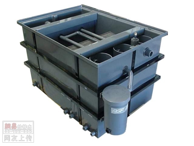
View of oil in Oil Barrel. Oil is pumped from pit and forms a slick on the surface for Bleed-Off through Valve on side of the Oil Barrel.
Operation is simple:
1) A Floating Oil Skimmer Pick-Up Device is positioned to float in a Pit or Tank where free-floating oil tends to accumulate.
2) The Float is provided with and located inside a Filter Barrel Screen to prevent floating debris form entering and clogging Floating Pick-Up Device.
3) The Floating Pick-Up Device and Barrel Filter are then connected to flexible tube, which is routed either directly or through plumbing to the Above Ground Oil Collection Barrel.
4) The Oil Collection Barrel is provided with Air Diaphragm Pump, Air Regulator and Off/On Switch. The Air Diaphragm Pump draws the oily water from the pit or tank and discharges it into the top of the Oil Collection Barrel.
5) The oily water must pass through a CELLOFOAM Oil Filter located 4” under the surface of the oily water. This traps the oil above the CELLOFOAM Oil Filter but allows the cleaned water to pass through for discharge back to the source from which it was drawn.
6) Next, the liquid must pass through an industrial rated Oil Coalescer. The Coalescer forces emulsified oils to adhere to the Coalescer surface, and after forming a large enough oil droplet, it breaks loose and floats to the surface where it collects with the rest of the free floating in the oil collection barrel.
6) The cleaned water then continues to drain down to the bottom of the oil collection barrel and where it exits and then drains up and out through the Stand Pipe Assembly, which sets the water level inside the Oil Collection Barrel.
7) The trapped oil can then be discharged through a Bleed Valve located on the side of the Oil Collection Barrel and disposed of properly.
Clean-Up is easy:
1) Turn off Air Diaphragm Pump and discharge the built-up head of oil from Oil Collection Barrel through side mounted Bleed Valve until only water discharges.
2) Drain the remaining water from Oil Collection Barrel through the Discharge Ball Valve located on Pipe Stand
3) Remove CELLOFOAM Oil Filter from Barrel and Pressure wash clean. The CELLOFOAM filter will require occasional cleaning by itself and can be removed without emptying the Oil Collection Barrel.
4) Pressure wash the Oil Collection Barrel until Clean and reposition CELLOFOAM Oil Filter
5) Restart Air Pump and refill the Oil Collection Barrel
6) The Barrel Filter in the pit may require occasional cleaning as well and should be inspected occasionally.
回复
3楼
Separation of oil from water in industrial waste streams is an initial step to obtain permit level discharge. Efficient oil/water separation is of prime importance in industrial waste treatment stages often required before final discharge.
The HEI corrugated plate separator is a sophisticated, compact, highly efficient gravity settling basin designed to fill this need.
The basic design of the HEI corrugated plate separator is shown below. When wastewater enters the separator inlet compartment, the velocity is slowed, allowing large solids to settle out in the sand collection compartment and large oil globules to float to the surface. The influent then passes through a distribution baffle and enters the plate pack compartment.
After passing through a quiescent zone, wastewater enters the corrugated plate pack. Here the finer oil droplets and settable solids are separated out by gravity. The de-oiled wastewater flows into the effluent compartment and rises toward the effluent weir.
Both the plate pack compartment and effluent compartment are provided with an adjustable weir. Height is adjusted to balance the hydraulic loads so that only oil is skimmed off the surface of the plate pack compartment. An oil layer is maintained in this compartment and is automatically skimmed due to the difference in specific gravity of oil and water.
At the heart of the HEI corrugated plate separator is the plate pack. The standard plate pack consists of fifty corrugated plates spaced on 3/4" centers. A cutaway view is shown below.
The plate pack is designed so that oil, as it separates from water, migrates to the underside of the plate above and collects in the peaks of the corrugations. The migration continues counter to the water flow toward the inlet of the plate pack. Sludge settles to the top of the next lower plate, collects in the valleys of the corrugations, and slides by gravity toward the outlet end of the plate pack.
The peaks of the corrugations at the inlet end are connected by vertical gutters to guide the collected oil of of the wastewater flow area. The same system is provided on the valleys at the outlet end for sludge disposal. The collection gutter prevents the re-entrainment of oil or sludge.
回复
4楼
MINERAL OIL AND RESIDUAL OIL WATER SEPARATOR
OIL OUTLET CONCENTRATIONS BEHIND THE SEPARATOR < 5 ppm
CAPACITIES: from 47 gallons/min to 9473 gallons/min
回复
5楼
MINERAL OIL AND RESIDUAL OIL WATER SEPARATOR
OIL OUTLET CONCENTRATIONS BEHIND THE SEPARATOR < 5 ppm
CAPACITIES: from 47 gallons/min to 9473 gallons/min
回复
6楼
MINERAL OIL AND RESIDUAL OIL WATER SEPARATOR
OIL OUTLET CONCENTRATIONS BEHIND THE SEPARATOR < 5 ppm
CAPACITIES: from 47 gallons/min to 9473 gallons/min
回复
7楼
The Ultracept® Process
From a surge pit, either above or below grade, contaminated water is pumped to the Ultracept® Oil/Water Separator. The separator, having been filled with clean water prior to start-up, then uses the clean water to promote and enhance waste separation. The water then travels through a series of chambers for its gravity discharge to a sanitary sewer. Through a unique skimming technique, the Ultracept® System isolates the waste for easy removal.
Ultracept Surge Pit Descri ption and Sketch
The minimum size for a surge pit is 4 x 4 x 4, which equals to approximately 450 gallon capacity, however, the larger the better. In some cases, existing tanks or old underground Separators can be used. When possible, a baffled surge pit as illustrated above is recommended. To the left is a top view of the basic Ultracept® Water/Cohesive Separator with waste oil holding chamber and polishing media tray.
The above image shows the back of the Ultracept® Water/Cohesive Separator with the optional waste oil holding tank. This model is recommended for situations that may have the potential of spills such as refueling areas.
回复
8楼
2
回复
9楼
3
回复
10楼
It provides optimum efficiency in gravity separation between two immiscible liquid fractions. The horizontal orientation of the Phase 3 modules provides a uniform and non-clogging flow through the coalescing tubes. The rectangular openings in its tubular construction allow for settling solids to pass through the coalescing media. The design versatility of the Phase 3 also eliminates the staging that is necessary with other incline and horizontal coalescing plates.
Features:
No pre-treatment.
High efficiency separation due to high surface area coalescing media.
No moving parts. (On standard units)
Easy cleaning.
Minimal maintenance.
All steel vessel construction.
Large solids settling area.
Applications:
Aviation
Chemical Processing
Machine Tools
Marine Terminals
Metal Processing
Oil Production
Petrochemical
Plastics
Power Plants
Processing Plants
Steel Mills
Storm Water Run-Off
Transportation
Utilities
Vehicle Washes
Water Treatment Plants
回复
11楼
TPL-Phase 3 Oil Water Separator
回复