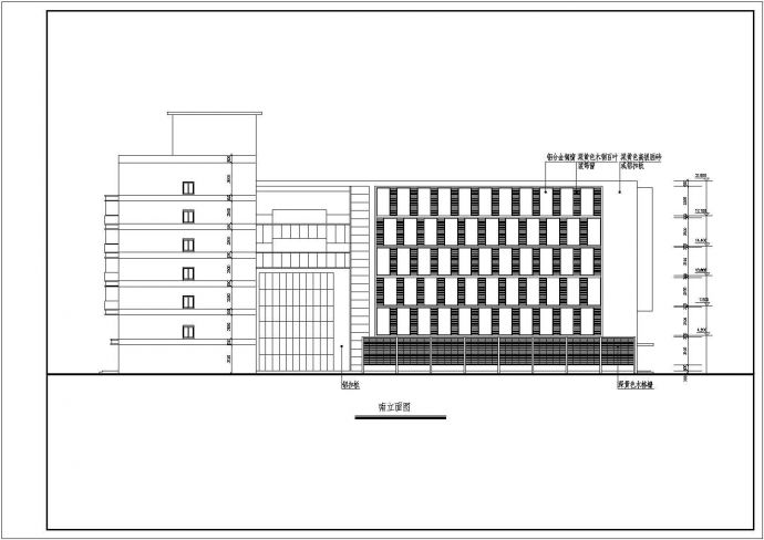
本图纸为某六层办公楼VRV多联机系统暖通设计图,图纸内容包括一~六层设备及管路布置平面图、各层系统图、总系统图、屋面设备布置图、设备表。

某六层办公楼VRV多联机系统暖通设计图_图1

某六层办公楼VRV多联机系统暖通设计图_图2

某六层办公楼VRV多联机系统暖通设计图_图3
点击展开全文
用户评价(1)
我要评论-
看乡过客
LV4
10
还不错,可以作为参考
2015-06-27
点击查看更多评论